
Converting engineering drawings to patent drawings means reformatting CAD or technical files so every view, line weight, and reference numeral satisfies USPTO Rule 37 CFR 1.84 or WIPO’s PCT Rule 11. A CAD export is not a patent figure by default; it must be redrawn, relabeled, and reformatted to meet formal filing standards. Skipping that conversion step is one of the fastest ways to trigger a drawing objection and lose months of pendency.
Most inventors assume their SolidWorks, AutoCAD, or Fusion 360 file is “basically done” once the design looks right on screen. In reality, patent offices judge drawings against a completely different rulebook than engineering software does. If you need a professional patent drawing conversion service that handles this transition end to end, that gap is exactly where PatentVisuals steps in, taking a raw CAD export and turning it into a filing-ready sheet an examiner will accept on the first pass.
This guide walks through why CAD files fail patent review, what USPTO and PCT rules actually require, and how to convert engineering drawings into patent drawings without losing weeks to draftsperson objections.
What Are Patent Drawings, and Why Isn’t a CAD Export Enough?
A patent drawing is a formal legal document, not an illustration. It defines the scope of an invention’s disclosure and, in design patent cases, the exact boundaries of what is protected. Examiners read drawings the way courts later read claims: literally, and without room for guesswork.
Quick answer: A CAD or engineering drawing shows how something is built. A patent drawing shows what is legally disclosed. The two documents serve different audiences and follow different rules, so one rarely converts into the other without deliberate reformatting.

Engineering drawings are optimized for:
- Manufacturing tolerances and dimensions
- Material callouts and assembly instructions
- Internal engineering review, not public legal disclosure
Patent drawings, by contrast, must satisfy formal standards for margins, line density, shading, numbering, and view selection before an examiner will even look at the substance of the invention. When those standards aren’t met, the application doesn’t fail on merit; it fails on formality, and that is almost always avoidable.
This distinction trips up a lot of first-time applicants, since a beautifully rendered CAD assembly can look far more “finished” than a simple black-and-white line drawing. Appearance isn’t the measure examiners apply, however. Compliance is. A hand-drawn sheet that follows 37 CFR 1.84 precisely will clear formal review faster than a photorealistic render that doesn’t, because the rule cares about reproducibility and legal clarity, not visual polish.
It also helps to remember that patent drawings become part of the public record once the application publishes. Anyone researching prior art, competing inventors, examiners years into the future, and even courts during litigation will reference these exact sheets. That permanence is part of why formal compliance matters so much more here than it does for an internal engineering file that gets revised freely as a design evolves.
Who Typically Needs to Convert Engineering Drawings Into Patent Drawings
This conversion comes up constantly across a few recurring groups, each with slightly different pressures.
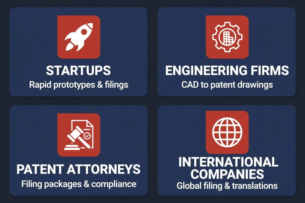
- Startups and inventors filing their first application: Often working directly from CAD files created for a prototype, without in-house knowledge of formal drawing rules.
- Engineering firms supporting outside counsel: Producing the technical geometry while an attorney handles claims, which means the drawing hand-off has to be clean enough to convert quickly.
- Patent attorneys and agents: Needing figures that match claim language precisely, since mismatched reference numerals between drawings and specification create their own objections.
- Companies filing internationally: Managing both USPTO and PCT requirements simultaneously, which raises the stakes on getting the conversion right the first time.
Regardless of who initiates the process, the underlying task stays the same: translate a technically accurate CAD file into a legally compliant disclosure document, without altering what the invention actually is.
Key Differences Between CAD Drawings and Patent Drawings
Before converting engineering drawings to patent drawings, it helps to see precisely where the two formats diverge. The table below summarizes the most common friction points teams run into during conversion.
| Feature | Engineering / CAD Drawing | Formal Patent Drawing |
|---|---|---|
| Purpose | Manufacturing and internal reference | Legal disclosure and claim support |
| Dimensions | Precise measurements shown | Generally omitted unless essential |
| Line weights | Varies by tool default | Uniform, solid black, reproducible at 2/3 scale |
| Color/shading | Often color-coded or rendered | Black and white; shading only for surfaces, not decoration |
| Labeling | Part numbers, tolerances, material specs | Reference numerals tied to the specification text |
| Views | As many as engineering needs require | Only views necessary to disclose the claimed invention |
| File format | DWG, STEP, native CAD formats | Filing-ready PDF or TIFF per office rules |
Because the source data is different, a direct export rarely satisfies either USPTO or PCT standards. Consequently, treating the CAD file as a starting reference, not a finished figure, saves considerable rework later.
USPTO Requirements for Converting Engineering Drawings to Patent Drawings
The primary rule governing US patent drawings is 37 CFR 1.84, and the USPTO’s own Manual of Patent Examining Procedure explains how examiners apply it in practice. Together, these documents cover paper size, margins, ink density, lettering height, and view types.

Core formatting rules examiners check first
- Sheet size: Either 21.0 cm x 29.7 cm (A4) or 21.6 cm x 27.9 cm (US letter)
- Margins: Minimum 1 inch (2.5 cm) at the top and left of every sheet
- Line quality: Durable, black, uniformly thick lines suitable for reproduction
- Reference characters: At least 0.32 cm (1/8 inch) in height, so numerals remain legible after reduction
- Scale: Every detail must stay clear even after a two-thirds reduction, since that’s the size used for publication
Quick-reference table: common USPTO drawing specifications
| Requirement | USPTO Standard (37 CFR 1.84) |
|---|---|
| Accepted paper sizes | A4 or US Letter |
| Minimum top/left margin | 1 inch (2.5 cm) |
| Minimum reference character height | 0.32 cm (1/8 inch) |
| Drawing medium | Solid black ink or equivalent; non-shiny paper |
| Color drawings | Allowed only after an approved petition (utility applications) |
| Shading | Permitted for surfaces; must not obscure reference numerals |
If informal drawings are filed first, applicants typically get roughly two months after a Notice to File Corrected Drawings to submit compliant sheets, so early conversion still saves a filing cycle even when time is tight.
For a deeper walkthrough of the full formal checklist, our complete guide to preparing patent drawings breaks down every subsection of the rule with annotated examples.
Where CAD exports typically fail 37 CFR 1.84
- Line weights vary across layers instead of reading as one uniform black
- Dimension lines, tolerances, and material call-outs remain visible and must be deleted
- Isometric or perspective views lack the orthographic views examiners expect
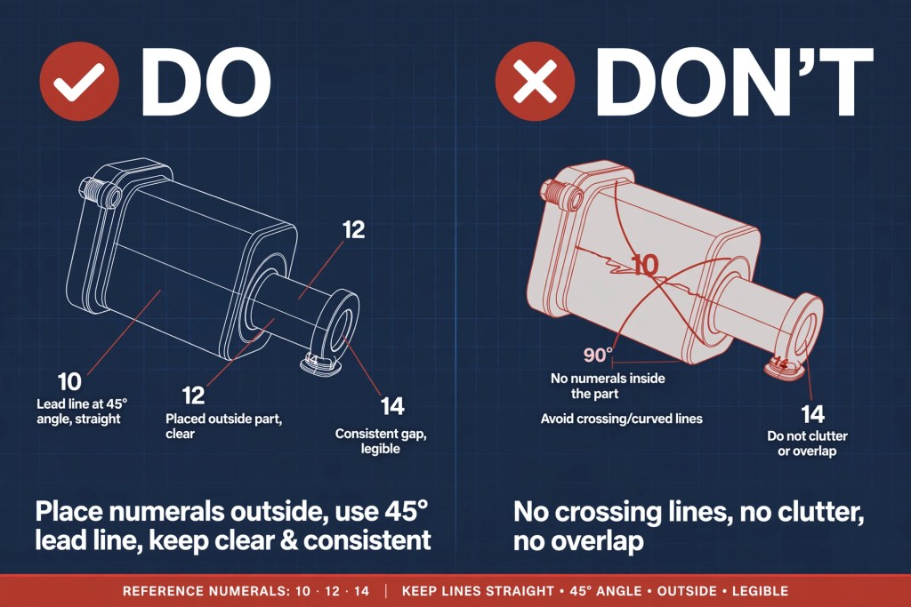
- Reference numerals are missing entirely, since CAD software labels parts, not claim elements
- Sheets bleed into the margin because CAD canvases aren’t sized to filing sheet dimensions
None of these issues reflect a flaw in the underlying invention. They reflect the gap between a file built for manufacturing and a document built for legal disclosure, and that gap is precisely what a proper conversion process closes.
Types of Views a Patent Drawing May Require
CAD software tends to default to a single perspective or isometric render because that’s what communicates a design fastest during product development. Patent drawings, however, often need several distinct view types working together to fully disclose an invention.
- Orthographic views (front, top, side): These form the backbone of most utility drawing sets, since they show proportions without the distortion a perspective view introduces.
- Sectional views: Used when internal structure needs to be shown, a sectional view cuts through the object along a defined plane and applies hatching to indicate the cut surface.
- Exploded views: Helpful for assemblies with multiple parts, exploded views separate components along an axis so the reader can see how pieces fit together.
- Perspective views: Occasionally added as a supplemental view to give context, though they rarely substitute for the required orthographic set.
- Flowcharts and block diagrams: For software, systems, or process inventions, flowcharts are treated as drawings under both USPTO and PCT rules and must follow the same line-quality standards as physical drawings.
Choosing the right combination matters more than including every possible view. Examiners expect enough views to understand the claimed invention completely, but padding a drawing set with redundant angles adds cost without adding disclosure value. A CAD file typically contains far more views than a patent application needs, so part of the conversion process is actively deciding what to leave out.
Line Weights, Shading, and Reproduction Quality
Line quality is one of the most frequently misunderstood requirements in the entire conversion process, largely because CAD software renders lines very differently than a patent drawing requires.
Engineering software often varies line weight by layer, by part type, or by rendering style, producing drawings with dashed hidden lines, colored highlights, or gradient shading that looks polished on screen. None of that survives the transition to a formal patent figure. USPTO and WIPO both require durable, uniformly thick, solid black lines with no color and no gradient effects, since the drawing must remain legible after significant reduction and repeated scanning.
Shading rules add another layer of nuance:
- Shading is allowed to indicate a surface, contour, or material characteristic.
- Shading must not obscure reference numerals or lead lines.
- Cross-hatching in sectional views should be uniform in spacing and angle.
- Heavy or excessive shading is one of the more common reasons draftsperson objections cite readability problems.
Because reproduction quality is tested at two-thirds scale, a line that looks perfectly clear at full size on a monitor can become illegible once printed smaller. Checking every sheet at reduced size before submission catches this problem early, rather than after an examiner flags it.
PCT and International Considerations When Converting Engineering Drawings
If the application will also be filed internationally, PCT Rule 11 adds its own layer of formatting requirements, administered by WIPO. The standards overlap heavily with USPTO rules but aren’t identical, which is why converting once for the US and assuming it covers every jurisdiction is a common mistake.
Under WIPO’s PCT drawing guidelines, drawings must use durable, uniformly thick black lines without color, and text on the drawing itself should be limited to what is genuinely indispensable, such as flowchart labels or circuit callouts. Sheet size is fixed at A4, and the usable surface area is capped, with no frame permitted around the drawing.
Because national phase entry can still trigger new objections even when PCT Rule 11 was followed at the international phase, applicants who plan to file abroad should convert their engineering drawings against the stricter of the two standards from the outset. Our article on how PCT drawing rules differ from USPTO requirements compares the two side by side in more detail.
File Formats and Electronic Filing Requirements
A drawing that passes every formatting rule can still be rejected if it’s saved in the wrong file type. Native CAD formats such as DWG, STEP, or IPT are source files, not deliverables, so the final conversion step always involves exporting to a format the receiving office actually accepts.
- USPTO electronic filing (EFS-Web / Patent Center): Accepts PDF format for drawings, with image resolution high enough to remain legible after scanning and reduction.
- PCT electronic filing: Typically requires PDF or TIFF, since the International Bureau converts non-XML submissions before publication and low-resolution files don’t survive that process cleanly.
- Resolution: Aim well above the minimum threshold; a drawing that looks acceptable on screen at low resolution frequently loses legibility once printed or archived.
- Compression: Avoid heavily compressed image formats, since artifacting around fine lines and small reference numerals can render them unreadable.
Getting the file format right doesn’t just satisfy a technical checkbox. It determines whether the drawing survives digitization, scanning, and archival intact for the life of the patent, so it deserves the same attention as line weight or margin size.
Step-by-Step: How to Convert CAD or Engineering Drawings Into Patent Figures
Converting engineering drawings to patent drawings follows a repeatable process once you know what examiners are actually checking for.

- Export clean line art from the CAD source. Remove dimensions, tolerances, and material annotations before anything else, since these elements have no place on a formal patent figure.
- Select the minimum necessary views. Choose only the views (front, side, section, perspective) that are needed to disclose the claimed invention clearly; extra views add clutter without adding legal value.
- Standardize line weights. Redraw or trace the export so every line is uniform, solid, and black, with shading reserved for surfaces rather than decoration.
- Apply reference numerals. Tie every numbered part back to the specification text, using consistent numbering across all figures in the set.
- Set the sheet to filing dimensions. Resize the canvas to A4 or US Letter with the correct margins before placing any artwork, rather than resizing after the fact.
- Add lead lines and labels correctly. Lead lines should be straight, not curved, and should not cross unnecessarily.
- Export to a filing-ready format. Convert the final sheet to PDF or TIFF at a resolution that survives two-thirds reduction without losing legibility.
- Proof against the checklist. Compare the finished sheet against 37 CFR 1.84 (or PCT Rule 11 for international filings) line by line before submission.
Working through these steps in order prevents the most expensive mistake in the whole process: discovering a formatting problem after the application has already been filed.
Common Mistakes When Converting Engineering Drawings to Patent Drawings
Even experienced engineering teams run into the same handful of issues repeatedly. Recognizing them early avoids a Notice of Draftsperson’s Objection later.

- Leaving dimension lines and tolerances in place. These belong in manufacturing documents, not in a legal disclosure.
- Using color or shaded renders instead of solid black lines. Utility applications require a petition before color is accepted at all.
- Undersized reference numerals. Anything smaller than 1/8 inch risks becoming illegible after the mandatory two-thirds reduction.
- Inconsistent numbering across figures. The same part must carry the same reference number on every sheet it appears on.
- Ignoring margin requirements. Artwork that bleeds into the margin is one of the most frequently cited formal deficiencies at both USPTO and WIPO.
- Treating the PCT and USPTO versions as identical. Small differences in margin size and usable surface area mean a drawing built for one office may still fail the other.
- Submitting native CAD files as the final deliverable. DWG or STEP files are source material, not a filing-ready drawing set.
- Including too many or too few views. Overloading a sheet with every CAD-generated angle adds clutter, while omitting a required view can limit what the drawing ultimately discloses.
- Skipping the reduced-scale proof. A sheet that looks clean at full monitor size can still fail the two-thirds reduction test that examiners apply during publication.
Most of these mistakes share a common root cause: treating drawing conversion as a final export step instead of a distinct formatting discipline with its own rulebook.
Expert Tips for Examiner-Ready Patent Figures
A few practices consistently separate drawing sets that clear examination on the first pass from those that generate office actions:
- Build drawings at a larger working scale than needed, then confirm legibility after simulating the two-thirds reduction examiners apply during publication.
- Keep a master reference-numeral list alongside the specification draft so labeling stays consistent as figures are added or revised.
- Route the CAD-to-patent-drawing conversion through someone who reviews against 37 CFR 1.84 daily, rather than treating it as a final CAD export step.
- When an application is bound for multiple jurisdictions, design the drawing set against the stricter combined standard from day one instead of redrawing later.
- Keep supplemental views (perspective, exploded, sectional) available even if not filed initially, since designated offices can request additional views after the fact.
- Version-control the drawing set the same way you’d version-control code. As claims get amended during prosecution, drawings sometimes need matching revisions, and having a clear history prevents confusion between sheet revisions submitted months apart.
Taken together, these habits shift drawing conversion from a reactive fix, done only after an objection arrives, into a planned part of the filing process. That shift is usually what separates applicants who sail through formal examination from those who spend an extra prosecution cycle correcting avoidable errors.
Design Patents vs. Utility Patents: Different Conversion Needs
Not every conversion follows the same rules. Utility patents use drawings to explain how an invention works, so views, cross-sections, and flow diagrams are common. Design patents use drawings to define exactly what is protected, so surface shading, complete view sets, and precise line work carry far more legal weight.

For three-dimensional articles, design applications typically require a minimum of seven standard views, each shown head-on rather than at an angle, along with proper surface shading to indicate contour. Missing even one required view can limit the scope of protection later. Our design patent drawing checklist walks through all twelve formal requirements examiners check first, and it’s worth reviewing before converting any CAD file intended for a design filing.
If your invention involves both structural function and distinctive appearance, you may need two separate drawing sets: one utility-style set for the functional disclosure, and one design-style set with full shading for the ornamental claim.
This distinction matters most at the conversion stage, since a CAD file exported for a utility disclosure rarely contains the full view set a design application needs. Planning which patent type you’re targeting before converting the file, rather than after, prevents a second round of redraws. For a broader refresher on formatting fundamentals that apply to both patent types, revisit our guide on patent drawing preparation before finalizing either drawing set.
Cost and Timeline: What to Expect When Converting Drawings
Budgeting for drawing conversion is easier once you know what drives the cost up or down. Several factors typically determine how long the process takes and what it costs:

- Complexity of the invention: A single mechanical part converts faster than a multi-component assembly requiring exploded and sectional views.
- Number of figures: More figures mean more sheets to format, number, and cross-check against the specification.
- Application type: Design patent sets generally require more views and more precise shading than a comparable utility drawing, which can extend turnaround time.
- Starting file quality: A clean, well-organized CAD file converts faster than a rough sketch or a file with excessive unnecessary detail.
- International filing plans: Building to the stricter combined USPTO and PCT standard from the start avoids a second conversion pass later.
Because a drawing objection typically adds two to four months to pendency, investing in a correct conversion up front is almost always cheaper than absorbing a delay after filing. Applicants who plan for this step early, rather than treating it as a last-minute formality, tend to move through examination with far fewer formal objections.
Conclusion
Converting engineering drawings to patent drawings is less about redrawing an invention and more about translating it into a format examiners are trained to accept without friction. CAD files give you accurate geometry; formal patent drawings give you a legally sound disclosure, and the two documents follow genuinely different rulebooks under 37 CFR 1.84 and PCT Rule 11.
Getting the conversion right the first time avoids the two-to-four-month delay that a drawing objection typically adds to pendency, and it keeps the file wrapper clean for the life of the patent. If your team would rather hand off that formatting work than absorb the risk of an office action, get your patent drawings prepared by PatentVisuals and move your application forward with figures built to clear examination the first time.
Frequently Asked Questions
Can I submit my CAD file directly as a patent drawing?
No. Native CAD formats like DWG or STEP aren’t filing-ready. They must be exported, cleaned of dimensions and tolerances, and reformatted to meet USPTO or PCT margin, line-weight, and numbering rules before submission.
What happens if my patent drawings don’t meet USPTO standards?
The USPTO issues a Notice of Draftsperson’s Objection or a formal office action requiring corrected drawings, which typically adds two to four months to pendency while the sheets are redrawn and resubmitted.
Are the USPTO and PCT drawing rules the same?
They’re closely aligned but not identical. Margin sizes, usable surface area, and a few administrative details differ, so a drawing set built strictly for one office can still generate objections when filed with the other.
Do design patents require different drawings than utility patents?
Yes. Design patents typically need a full set of standard views, often around seven for a three-dimensional article, along with surface shading to define the claimed ornamental appearance, while utility patents focus on views that explain function.
How long do I have to fix informal drawings after filing?
After a Notice to File Corrected Drawings, applicants generally have about two months to submit compliant formal drawings, though timelines can vary by case.
Can color drawings be used in a patent application? Color is accepted in most design applications. For utility applications, color is allowed only after filing a petition explaining why it’s necessary and paying the associated fee.
Who should convert engineering drawings into patent drawings?
Anyone preparing a filing can attempt the conversion, but because a single formatting error can trigger an objection, many applicants route the work through a service that checks every sheet against 37 CFR 1.84 or PCT Rule 11 before submission.
What file format should finished patent drawings be saved in?
Finished drawings are typically saved as PDF for USPTO electronic filing, or PDF/TIFF for PCT submissions, at a resolution high enough to remain legible after scanning and two-thirds reduction.
Does converting a CAD file into a patent drawing change the invention itself?
No. The conversion changes formatting, not substance. Dimensions, tolerances, and material call-outs are removed because they aren’t part of the legal disclosure, but the underlying structure and function of the invention stay exactly the same.
